The Math of the Terminal Donut
Shinwoo PARK
This post was migrated from my Velog
You can see the original post here.
This version fixes various things such as the dark background, LaTeX, and errors in the content.
If there are any parts that need further correction, please contact shinwoo.park@psw.kr
Original publication date: 2022/12/4
Updated: 2025/7/3
Haven't you seen something like this at least once?
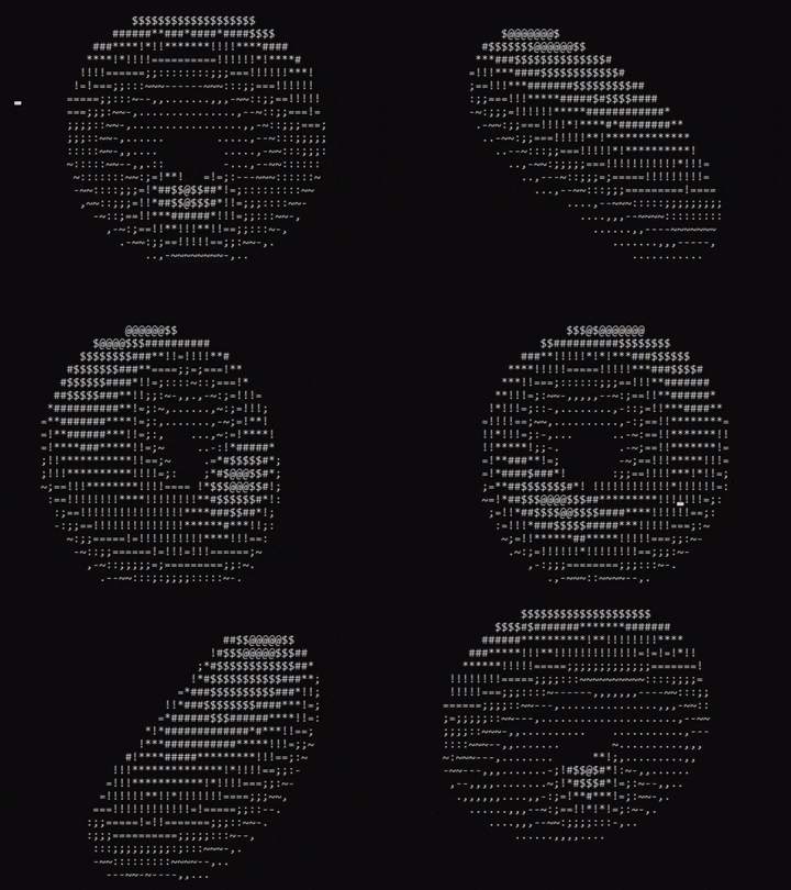
A black screen, with a rotating 3D donut made out of white special characters.
It definitely looks like a simple program, but somehow it is oddly mesmerizing to watch.
This is Donut.c.
Drawing images like this using ASCII strings is called ASCII Art.
"Come on, it's just printing text in a console window."
But it is not something to take lightly.
Because anything related to graphics opens up a profound world of mathematics once you dig into it.
In this post, I want to try understanding that mathematics.
Donut.c
My interest in this console donut began with a YouTube video.
That video was "why you NEED math for programming".
Near the end of the video, it briefly explains the mathematical principle behind how the donut is rendered in ASCII code.
After hearing that, I got curious and started searching the internet.
Surprisingly, there were not as many articles about it as I expected.
There were only a few brief Korean introduction posts and some English articles explaining the complicated mathematical principles.
At first, I hesitated to read them because they combined English with complex mathematics, but once I committed to reading them, they were manageable.
So now, let's begin the real analysis.
The mathematical principles in this post are based on this article.
About ASCII Art
First, let's look at how brightness is generally represented in ASCII Art.
The place where we will output ASCII Art is the terminal, and terminals usually have a dark background with bright text.
Therefore, if the density of pixels within the space occupied by one character is high, we can treat it as a bright color; if the density is low, we can treat it as a dark color.
The following 12 characters represent that simply.
.,-~:;=!*#$@
The left side has the lowest density within a fixed area, so it is the darkest, while the right side has the highest density within a fixed area, so it is the brightest.
Mathematical principles
First, let's think about how to implement it.
We need two things.
- Draw the shape of the donut
- Represent brightness on the donut's shape
Now then, let's begin with some simple mathematics used in a 3D first-person viewpoint.
The figure above shows a person sitting in front of a screen and looking at an object behind the screen.
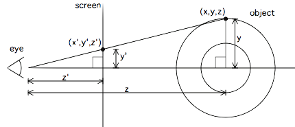 To draw a 3D object in 2D, we project each point (x,y,z) in 3D onto a plane located z′ away from the viewer.
Then that point becomes (x′,y′).
Since we know the coordinates of each point of the 3D object and need to determine where they should be projected in 2D, we must find x′ and y′ using x and y. (Since z′ is a constant, let us call it K1.)
Written as a mathematical formula, K1y′=zy
Moving z′ to the other side gives y′=zyK1
The same applies to x: x′=zxK1
Therefore, the projection equation becomes (x′,y′)=(zK1x,zK1y).
K1 can be set arbitrarily according to the desired field of view for the 2D window. For example, if there is a 100x100 window, the view will be centered at (50, 50). If you want to view an object in 3D space that is 5 units away from the viewpoint and has width 10, then the projection of the point at x=10, z=5 must appear on the screen, so:
- x′<50 must hold
- that is, z10K1<50 must hold
- that is, K1<25 must hold
Also, while projecting many points, there may be cases where we need to project points that have the same x and y but different z values, so we will create a z-buffer that stores the z coordinate for everything we draw. With a z-buffer, when placing a point at a location, we can check whether it is in front of what was already there.
Also, the z-buffer can help with computing and buffering z−1=z1 for the following reasons.
- If z−1=0, then z is close to infinity, so we can set the z-buffer's default value to 0 and treat the background as having infinite depth.
- It can be reused when calculating x′ and y′. (z−1=z1, and by dividing by z in advance, we can avoid dividing by z twice and compute a little more efficiently.)
The donut (solid of revolution)
Now we need to think about how to create the donut's shape.
Fortunately, a donut is a solid of revolution, so we can obtain each point using the following principle.
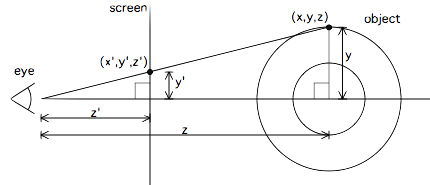 As you can see, there is a circle of radius R1 centered at the point (R2,0,0).
The circle centered at R1 can be drawn by rotating it from 0 to 360 degrees.
Let the variable that changes from 0 to 360 degrees be θ.
Written as an equation, it becomes the following.
(x,y,z)=(R2,0,0)+(R1cosθ,R1sinθ,0)
With this equation, we can obtain one circle.
Now let's rotate this circle along the 2y-axis. You can probably already tell that this produces the donut shape.
To rotate this circle around the y-axis, we can use a rotation transformation matrix.
Since we need to rotate it along the y-axis, if we multiply by the 3D y-axis rotation transformation matrix, we get the following expression.
=(R2+R1cosθ,R1sinθ,0)⋅cosϕ0−sinϕ010sinϕ0cosϕ((R2+R1cosθ)cosϕ,R1sinθ,−(R2+R1cosθ)sinϕ)However, we want to implement this donut so that it rotates around more than one axis, so we multiply it by two additional rotation transformation matrices.
Also, let the angles used in those two rotation transformation matrices be called A and B.
The expression is as follows.
Now we have the coordinates of a donut centered at the origin (0,0,0) and rotating continuously according to the angles A and B.
To actually project this onto the screen, we assume that the viewer's coordinates are (0,0,0) and move the donut in front of the viewer.
To move the donut in front of the viewer, we need to add the distance between the viewer and the donut to z.
Let this distance between the viewer and the donut be K2.
Now the formula for finding the actual (x′,y′) is the following.
(x′,y′)=(K2+zK1x,K2+zK1y)
And the formula for finding (x,y,z) is the following.
xyz=(R2+R1cosθ)(cosBcosϕ+sinAsinBsinϕ)−R1cosAsinBsinθ(R2+R1cosθ)(cosϕsinB−cosBsinAsinϕ)+R1cosAcosBsinθcosA(R2+R1cosθ)sinϕ+R1sinAsinθTo optimize as much as possible, at the programming stage we will not use matrix multiplication directly, but instead use the calculation formula above, and we will also precompute values such as (R2+R1∗cosθ) so they can be reused in the expression.
Brightness
Now we know where to place points, but we still do not know the brightness of each point.
The mathematical concept needed to calculate luminance is the surface normal.
Once we obtain this normal, we can compute the dot product between the normal and the direction of the light, and this dot product contains the cosine of the angle between the normal and the light direction.
Since the dot product of vector a and vector b is a⋅b=∣a∣∣b∣cosθ,
if this dot product is greater than 0, then cosθ>0, which means the point at that position is facing the light and is therefore bright; if it is less than 0, the point is not facing the light and is therefore dark.
In other words, the larger the dot product is, the more light falls on that point.
But if you think about it, this normal vector is actually very easy to obtain.
Because the vector from (0,0,0) to the final (x,y,z) becomes the normal vector at the point (x,y,z).
Therefore, we can write the expression again just as we did with the rotation transformation matrices.
The difference here is that the starting point is (cosθ,sinθ,0).
This does not represent the exact values of x, y, and z, but only the direction using cosine and sine for each θ. (Its magnitude is not exact.)
Now then, we need to choose the light direction.
How about shining light from above and behind the viewer?
Then the light vector becomes (0,1,−1).
Now let us compute the dot product of the normal vector above and this light vector.
Now the last thing left is to choose the constants.
The constants not yet chosen are R1 and R2, which determine the donut's overall size and ring thickness; K1, which determines scale; and K2, which represents the distance between the viewer and the donut.
First, R1 and R2 are set to 1 and 2 respectively, and K2 is set to 5.
For K1, since it determines scale and therefore depends on the screen size (the number of ASCII characters that can be displayed on one screen), we can build the following equation.
First, the maximum horizontal extent the donut can have (the maximum x-coordinate) is R1+R2, and z is 0.
If we want that point to appear around the 83 position of the screen width,
screen_width * 3/8 = K1 * (R1+R2) / (K2 + 0)
screen_width * K2 * 3 / (8 * (R1+R2)) = K1
we can write it as above.
Final code
Therefore, the final code in Python and numpy is as follows.
import numpy as np
screen_size = 40
theta_spacing = 0.07
phi_spacing = 0.02
illumination = np.fromiter(".,-~:;=!*#$@", dtype="<U1")
A = 1
B = 1
R1 = 1
R2 = 2
K2 = 5
K1 = screen_size * K2 * 3 / (8 * (R1 + R2))
def render_frame(A: float, B: float) -> np.ndarray:
    cos_A = np.cos(A)
    sin_A = np.sin(A)
    cos_B = np.cos(B)
    sin_B = np.sin(B)

    output = np.full((screen_size, screen_size), " ")
    zbuffer = np.zeros((screen_size, screen_size))

    cos_phi = np.cos(phi := np.arange(0, 2 * np.pi, phi_spacing)) # (315,)
    sin_phi = np.sin(phi)
    cos_theta = np.cos(theta := np.arange(0, 2 * np.pi, theta_spacing)) # (90,)
    sin_theta = np.sin(theta)

    circle_x = R2 + R1 * cos_theta
    circle_y = R1 * sin_theta

    x = (np.outer(cos_B * cos_phi + sin_A * sin_B * sin_phi, circle_x) - circle_y * cos_A * sin_B).T
    y = (np.outer(sin_B * cos_phi - sin_A * cos_B * sin_phi, circle_x) + circle_y * cos_A * cos_B).T
    z = ((K2 + cos_A * np.outer(sin_phi, circle_x)) + circle_y * sin_A).T
    ooz = np.reciprocal(z)
    xp = (screen_size / 2 + K1 * ooz * x).astype(int)
    yp = (screen_size / 2 - K1 * ooz * y).astype(int)
    L1 = (((np.outer(cos_phi, cos_theta) * sin_B) - cos_A * np.outer(sin_phi, cos_theta)) - sin_A * sin_theta)
    L2 = cos_B * (cos_A * sin_theta - np.outer(sin_phi, cos_theta * sin_A))
    L = np.around(((L1 + L2) * 8)).astype(int).T
    mask_L = L >= 0
    chars = illumination[L]
    for i in range(90):
        mask = mask_L[i] & (ooz[i] > zbuffer[xp[i], yp[i]])
        zbuffer[xp[i], yp[i]] = np.where(mask, ooz[i], zbuffer[xp[i], yp[i]])
        output[xp[i], yp[i]] = np.where(mask, chars[i], output[xp[i], yp[i]])
        return output
def pprint(array: np.ndarray) -> None:
    print(*[" ".join(row) for row in array], sep="\n")

if __name__ == "__main__":
    for _ in range(screen_size * screen_size):
        A += theta_spacing
        B += phi_spacing
        print("\x1b[H")
        pprint(render_frame(A, B))